Camera Controls
ARMOR provides four virtual camera modes for navigating the 3D viewport. Each of these can be set as a gesture action for dragging on the 3D view.
Camera Modes
| Action | Description |
|---|---|
| Orbit | Rotate the camera around a fixed target point |
| Dolly | Move the camera forward and backward along the view axis |
| Pan | Translate the camera vertically or laterally in the view plane |
| Tilt | Rotate the camera in place |
Gestures
You may make use of a set of intuitive, multi-touch gestures to maneuver your camera and its target. These can be customized using the sheet that is toggled using the camera icon button in the lower left.
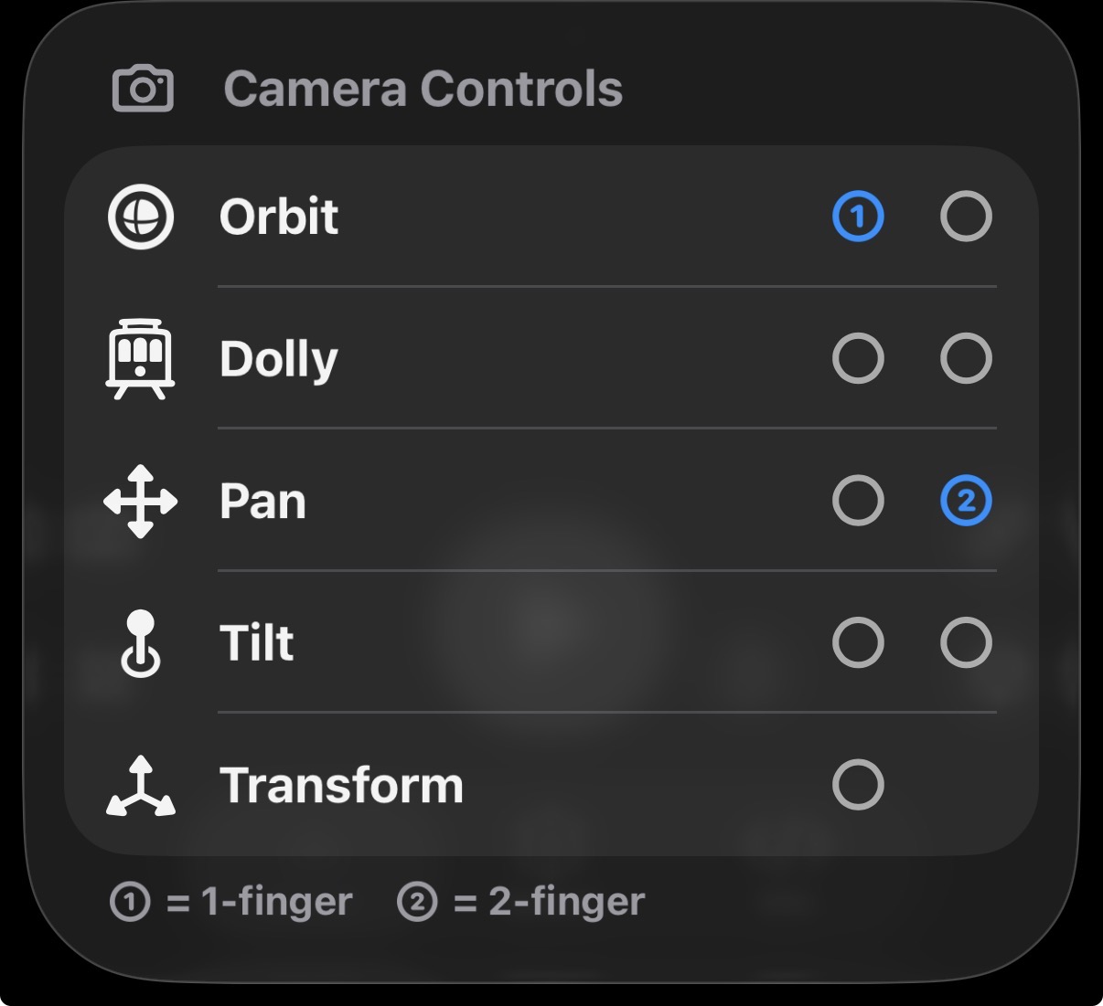
The actions corresponding to one and two finger dragging are selectable from each of the camera modes above.
- One-finger drag — primary action.
- Two-finger drag — secondary action.
- Pinch — zoom in/out the camera’s field of view.
Reset Camera
If you have orbited, panned, or zoomed away from the robot, open the camera menu and choose Reset Camera. It sits below the four camera modes and returns the virtual camera to its default framing of the robot. Reset Camera appears only in the Virtual view, because the camera in the Spatial view is your device.
View Options
The button below the camera button opens View Options, a sheet on iPhone and iPad and a menu on Mac. It holds toggles for optional entities in the 3D scene:
| Toggle | What it shows |
|---|---|
| Contact | The contact surfaces as a set of glowing edges |
| Grid | A grid in the X and Y directions |
| Axes | The X, Y, and Z axes as red, green, and blue arrows |
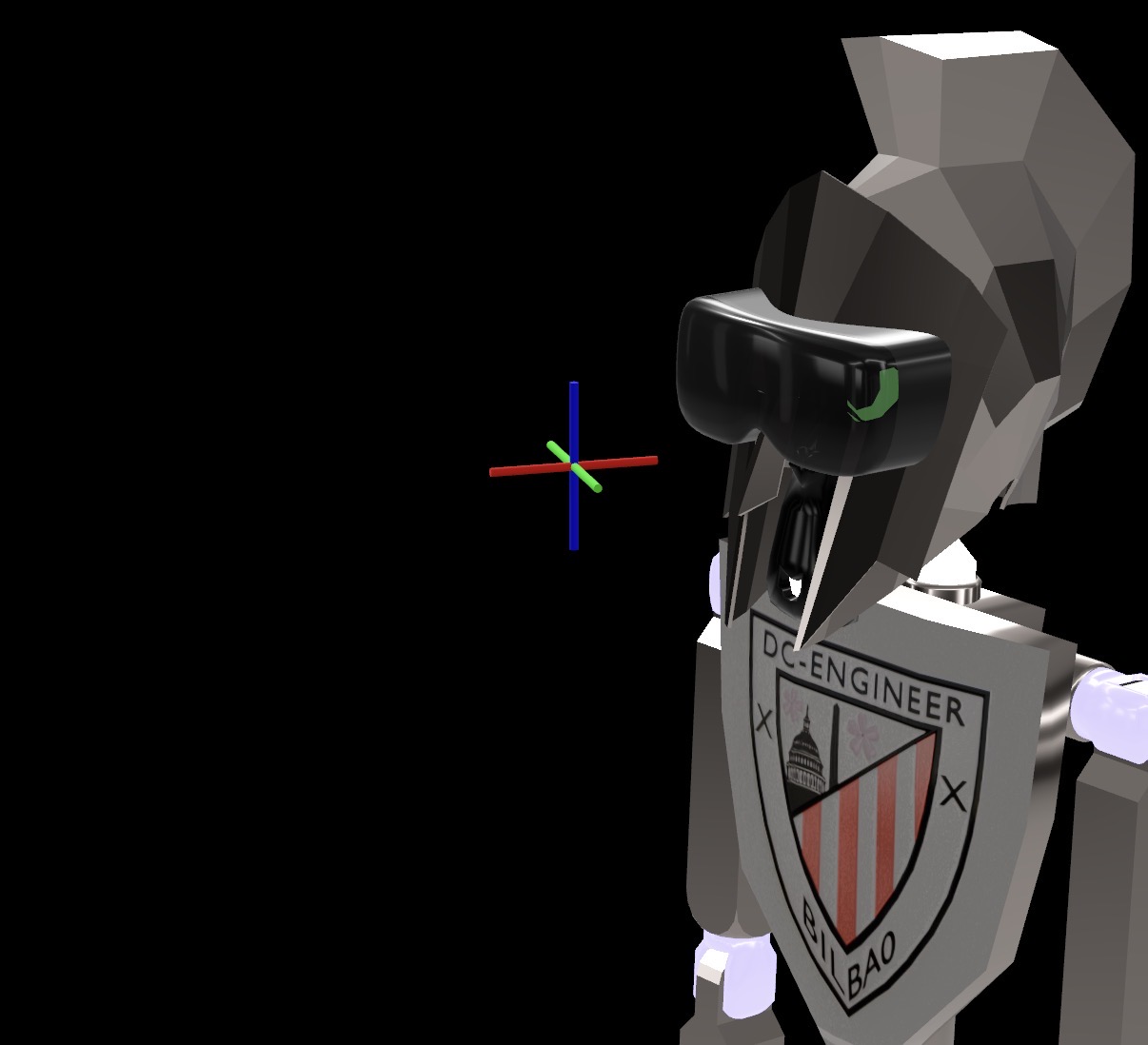
| Orbit Target | A 3-axis crosshair at the current orbit pivot point |
| Joints | A skeleton overlay of the robot’s joints, described below |
Orbit Target Indicator
Enable Orbit Target to show a 3-axis crosshair at the current orbit pivot point. The indicator scales proportionally to the camera distance.
Joints Overlay
Enable Joints to draw the robot’s kinematic skeleton over the model. For every joint it shows:
- the parent and child frames of the joint,
- a line connecting the two frames, and
- an indicator for the joint’s active axis, the axis it rotates or slides along.
The overlay is sized from the layout of the robot’s joints, so it stays readable on a small desktop arm and does not vanish on a large robot. During a simulation the markers follow the joints as they move, including a free-floating base such as the Bouncing Ball. In a multi-robot world, the overlay is drawn for every robot in the scene. The setting is remembered between launches.
It is useful for checking where each joint sits and which way it moves before you press Play. To change a joint, see Joints.
Next Steps
- Augmented Reality for viewing the robot in the real world.
- Joints for editing the joints the overlay shows.
- XML Viewer for inspecting the generated URDF and MJCF.