Joints
In a robotic system’s kinematic chain, a joint is the fundamental connection that defines the relative motion between two structural links. Much like the human body, the type of joint determines exactly how the attached parts can move. For instance, you might use a revolute joint to model a spinning shoulder or a knee hinge, a prismatic joint to constrain a linear sliding track, or a free/floating joint to represent the unconstrained motion of a drone traversing 3D space.
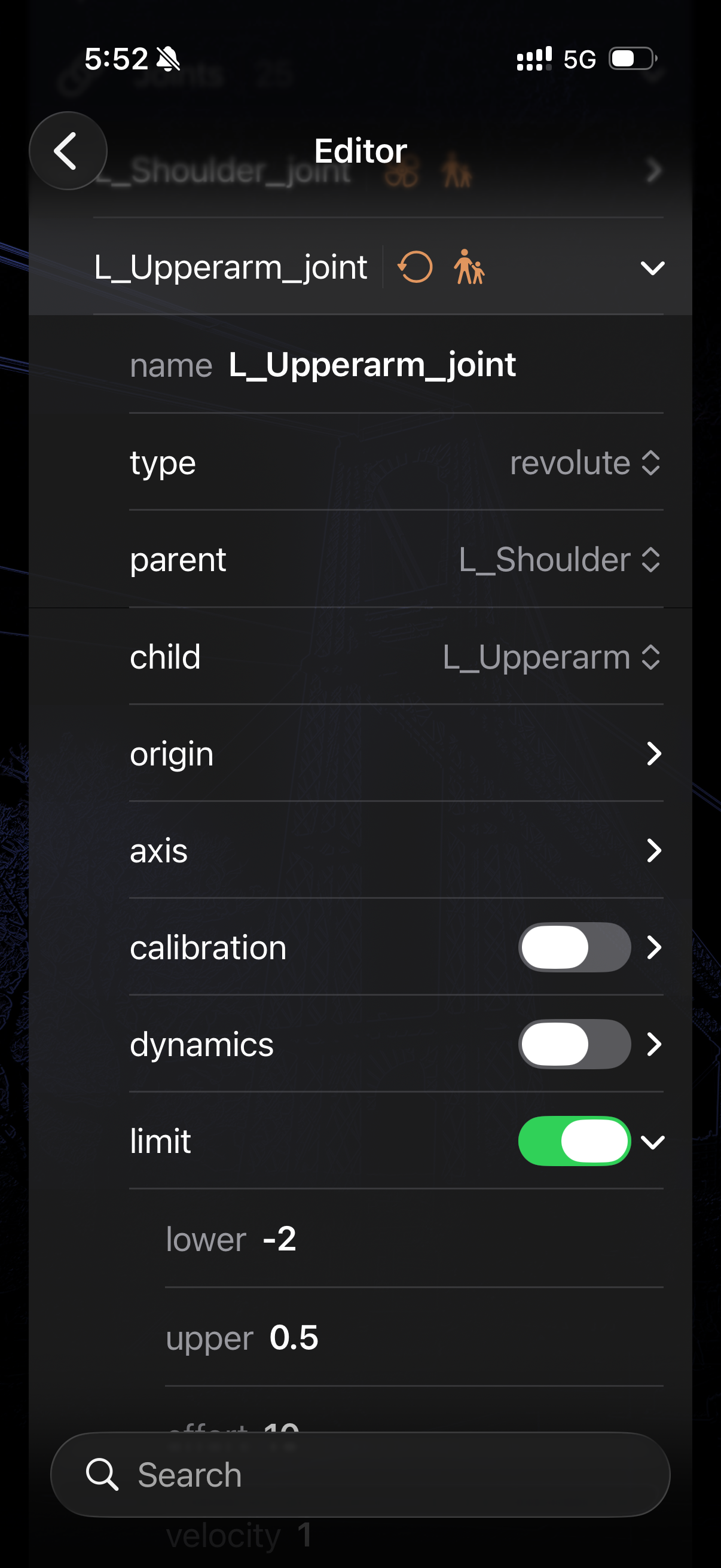
ARMOR allows you to configure joint limits, damping, and initial poses dynamically. Each field in the editor maps directly to a property in the underlying URDF — allowing you to work with structural form controls rather than writing raw XML by hand. For the complete specification, see the official ROS URDF joint documentation.
Editor Interface
When managing a joint’s properties in the ARMOR editor, the input methods are structurally mapped to prevent formatting errors and guarantee URDF validation:
- Numeric and String Data: Continuous properties like position limits, coordinate vectors, or string names are handled using standard text fields.
- Categorical Data: Constrained properties that require specific keywords (such as the joint
type) utilize pickers to ensure valid selections. - Parent and Child Links: Although the official URDF specification treats
parentandchildtags as freeform text strings, ARMOR strictly secures this relationship by using a picker that limits your options exclusively to the links that already exist within your model’s structured hierarchy.
Joints can be edited in two ways:
- Editor Panel — access all joints in a searchable list, organized into disclosure groups.
- Wizard Sheet — tap the button in the lower right of the 3D view to edit the selected joint one property at a time.
See Robot Editor for a full description of each variant.
URDF Joint Structure
A URDF <joint> tag specifies multiple distinct elements governing its kinematics and physical properties. All defined fields in the URDF standard are fully accessible within the ARMOR editor:
Core Properties
| Field | Description |
|---|---|
| Name | A string uniquely identifying the joint within the robot. |
| Type | Selecting the joint’s kinematic behavior (mapped via picker). |
| Parent Link | The foundational link attached to the joint (mapped via constrained picker). |
| Child Link | The dependent link whose movement is dictated by the joint (mapped via constrained picker). |
Geometry & Kinematics
| Field | Description |
|---|---|
| Origin | The spatial transform setting the position (x, y, z) and orientation (roll, pitch, yaw) of the joint frame relative to the parent link frame. |
| Axis | A normalized vector (x, y, z) defining the axis of rotation for revolute constraints or the axis of translation for prismatic joints. |
Limits (revolute & prismatic)
The Limits block establishes the physical boundary conditions and maximum exertion capabilities of the joint:
| Field | Description |
|---|---|
| Lower | Minimum position in radians (revolute) or metres (prismatic). |
| Upper | Maximum position in radians (revolute) or metres (prismatic). |
| Effort | Maximum force or torque the joint can transmit. |
| Velocity | Maximum velocity the joint can physically reach. |
Dynamics
Controls how the joint behaves under dynamic simulation conditions (e.g. in MuJoCo):
| Field | Description |
|---|---|
| Damping | Resistance proportional to velocity. Higher values produce smoother, slower motion. |
| Friction | Static friction inherent tightly clamped at the joint junction. |
Advanced Constraints
| Field | Description |
|---|---|
| Calibration | Used to set the reference rising or falling positions for the joint’s absolute reference point. |
| Mimic | Forces the joint to mimic the position of a different joint in the system, mathematically bound utilizing a multiplier and offset. |
| Safety Controller | Determines joint movement boundaries dynamically (soft limits, k_position, k_velocity) to gently prevent self-collision or over-exertion as the joint approaches its hard boundaries. |
Joint Types
| Type | Degrees of Freedom | Notes |
|---|---|---|
revolute |
1 (rotation, limited) | Most common for arm joints |
continuous |
1 (rotation, unlimited) | Wheels, spinners |
prismatic |
1 (translation, limited) | Linear actuators |
fixed |
0 | Rigid connection between links |
floating |
6 (rotation and translation) | Unconstrained motion (drones) |
planar |
3 (translation/rotation) | Moving on a flat 2D plane |